

Introduction
Requirements for Nanoparticles for Oilfield Use
Silica Nanoparticles for Stabilization of CO2 Foams for EOR and as “Waterless” Fracturing Fluids
Multi-scale Design of CO2 Foam Process
Ultra-dry CO2 Foams as “Waterless” Fracturing Fluids
Fly Ash Nanoparticles for Stabilization of CO2 Foams
Nano-Milling of Fly Ash
Foam Stability with Fly Ash
Foam Flow Experiments
Magnetite Nanoparticles for Produced Water Treatment and Other Uses
Synthesis of Iron-Oxide Paramagnetic Nanoparticles
Magnetic Removal of Microscopic Oil Droplets from Produced Water
Magnetic Removal of Remnant Polymer in Produced Water from Polymer EOR
PMNP-Based Removal of Divalent Cations from Hard Brine
Other Uses of Iron-Oxide Paramagnetic Nanoparticles. Use of Temperature-Responsive Polymer Gel and PMNPBased Heating for Improved Conformance Control
PMNP-Based Heating for Flow Assurance for Subsea Oil/Gas Pipelines
Use of PMNPs as “Contrast Agents” for Enhanced Reservoir Imaging
Conclusions
Introduction
Novel nanoscale structured materials, in the form of solid composites, complex fluids, and functional nanoparticle-fluid combinations, are bringing major technological advances in many industries. The recent, explosive advances in development of functional nanoparticles and their novel use in a wide variety of medical, biological, electronics and engineering applications, offer truly exciting and unique opportunities for the upstream oil industry. This is because the key processes for the oil exploration and production largely occur in porous rocks deep underground, and the nano-size particles that are engineered to carry out specific tasks in remote oil reservoirs can now be made to flow long-distance through rock pores, reach the target location, and perform the required function(s). Fig. 1 clearly illustrates this advantage of using nanoparticles: With an appropriate surface coating, 96% of a highly concentrated dispersion (18.7 wt.%) of 5-nm silica nanoparticles that had been injected into a very tight (10 md) limestone core came out in the effluent water (Roberts et al., 2012). This drastically contrasts with the almost immediate filtration of colloidal dispersions when injected into even a high-permeability reservoir rock. This means that a broad spectrum of applications of colloidal particles developed for more than 100 years, which was hitherto impossible to utilize for oil/gas reservoirs because of their almost immediate filtration, can now be utilized. For example, the solid core of the nanoparticles can be superparamagnetic, piezoelectric, or catalytic. Spurred in part by the SPE Workshops and Forums on the nanotechnology application development for E&P, held in 2008 (Dubai, UAE), 2009 (Kuala Lumpur, Malaysia), 2010 (Cairo, Egypt), 2011 (Farro, Portugal), 2012 (Noordwijk, The Netherlands), and 2013 (Kyoto, Japan), there is now a widespread interest in the upstream oil industry on the nanotechnology application developments. In view of the extensive advances made in other industries, the near-term applications will be the adaptation of what is already developed in those industries, i.e., harvesting the “low-hanging” fruits.

Requirements for Nanoparticles for Oilfield Use
In synthesizing nanoparticles (NPs) for oilfield operations, a number of important and critical requirements need to be satisfied, distinct from the above mentioned medical and biological applications. The extensive technology already developed in those disciplines cannot be directly utilized because of the unique nature of oil and gas reservoirs and fluids in them. Unlike the human bodies whose temperature and body fluid salinity is uniform, the temperature of oil reservoirs can vary from ambient to above boiling-point temperature and water can be from almost fresh water to a brine with salinity as high as 22 wt.%. Therefore, any NPs that are to carry out their design function should be able to withstand such harsh environments, remaining as individual nano-size particles without aggregation and maintaining their surface functionality intact for a sufficiently long enough time during their stay inside the reservoir or downhole at the wellbore. Another important distinction from human body application is that the length scale and time scale for reservoir applications are typically in kilometers and months, respectively, so that the NPs should be able to survive the long-distance transport with virtually no adsorption of NPs in rock pores. Properly surface modified silica and iron oxide nanoparticles have demonstrated minimal retention in porous media, as demonstrated by a comprehensive series of transport experiments, which were supported by modeling work (Yu et al., 2010; Zhang et al., 2016; Zhang et al., 2015). For practical oilfield applications, the third distinction is probably most important: While the biomedical application generally requires only a small amount of NPs and their recovery and regeneration for re-use is a non-issue, for oilfield applications for which a large- volume NP usage would be generally required, their regeneration and re-use is important not only for their economic usage, but also for their environmental and safety benefits. The possibility of repeatedly re-using the NPs for certain oilfield operations, instead of the chemicals that are currently used and which may not be “green”, opens up the exciting potential of making many oilfield operations environmentally safe and friendly.
In the next Section, the use of surface-treated silica nanoparticles as CO2 foam stabilizer is first described, followed by the potential use of ultra-dry but stable CO2-in-water foam as a “waterless” fracturing fluid for unconventional reservoir development. In Section III, the use of paramagnetic nanoparticles (PMNPs) to remove certain target “contaminants” from the produced water will be described. Some other applications of PMNPs are also described in the section.
Silica Nanoparticles for Stabilization of CO2 Foams for EOR and as “Waterless” Fracturing Fluids
Although CO2 EOR is successfully and economically practiced on large scale in U.S. and elsewhere, the method suffers the difficulty of poor oil sweep efficiency, mainly due to the very low viscosity of CO2. In order to improve the oil displacement efficiency, extensive research on the use of surfactant-stabilized CO2 foams has been carried out. A great challenge for the foam application for EOR is maintaining its long-term stability in the reservoir, especially for the high-salinity and/or high-temperature reservoirs where the commonly used surfactants tend to either degrade or precipitate. NPs being solid, the NP-stabilized foams generally have a more robust stability than the surfactant-stabilized foams; and are more tolerant of the high-salinity and high-temperature conditions. Prompted by the above benefits, an active research effort has been made as described briefly below. Because use of NP-stabilized CO2 foams for EOR application is a new research area, it requires multiple development steps starting from the optimal surface coating design for NPs, to the injection of an aqueous NP dispersion into the reservoir at which CO2 EOR operation is either already on-going or is planned, so that NP-stabilized CO2 foam performs properly in the reservoir. Therefore, the multi-scale design of NP-stabilized CO2 foam process is described briefly below.
Multi-scale Design of CO2 Foam Process
Fig. 2 schematically shows the design strategy for developing a NP-stabilized CO2 foam field trial, which builds in complexity from the initial, laboratory benchtop characterization of NPs up to field-scale modeling (Worthen et al., 2015). The first step of NP stability characterization, usually in the reservoir-condition brine at reservoir temperature, allows rapid screening of various NP candidates, where unstable particles are excluded from further testing. The proper design of NP coatings is key to passing this step, as described in detail by Worthen et al.(2013a; 2013b). In the second step, single-phase flow experiments are carried out to ensure that the NPs themselves can be transported through reservoir rock with minimal retention. Next, foam experiments are initially performed in small beadpacks or sandpacks, which can be quickly carried out at different process conditions. In the next step, corefloods are carried out to demonstrate feasibility of foam generation and transport in reservoir rock with the reservoir-condition fluids (without and with oil) at reservoir temperature and pressure. Results from the corefloods are then modeled at the core-scale to evaluate modeling techniques. Finally, the field-scale modeling is performed to evaluate whether to proceed with the development of a field trial, and to design the pilot test. Successfully designing a NP-stabilized foam process thus requires the above multi-scale investigation, as described in more detail by Worthen et al.(2015). Some of the important steps are briefly described below.

a) Stability of NPs in brine: So far with only a few exceptions, silica nanoparticles have been employed for CO2 foam process design. To investigate the silica nanoparticle’s stability, i.e., under what conditions and how rapidly the aggregation of a candidate nanoparticle occurs, the nanoparticle dispersion that is either obtained from a vendor or synthesized in-house needs to be characterized. The initial size distribution of the nanoparticles is first measured by dynamic light scattering (DLS) and transmission electron microscopy (TEM). The stock suspension is then diluted in the reservoir brine at different proportions to obtain the desired nanoparticle concentration for the study of the aggregation. The samples are usually prepared at two different pH levels, the low pH value typically chosen to be close to the pH of CO2-saturated water; and the higher pH value that of a typical reservoir, without CO2.
b) Transport of NP dispersion in porous media: Before the NP transport test is carried out in reservoir rock samples which in many cases either are not available or should be employed for only limited testing, sand columns which are packed with well-characterized sand grains can be employed, especially when the candidate reservoir’s main lithology is sandstone. Understanding the NP retention in reservoir rock is important to predict their transport at the field scale, and minimal retention of NPs is desirable. For example, as measured by Aroonsri et al.(2013), silica NPs showed little retention in a consolidated Boise sandstone at pH 4 and 8 in 9.6% TDS brine. The percentage of injected NPs transported through a sandstone was 91.6% (pH 4) and 97.7% (pH 8), respectively, which indicates that the surface treatment to NPs imposes sufficient repulsion to overcome the attraction onto the sandstone at the high salinity condition.
c) Generation of CO2 foam and its stability in porous media: Because the purpose of CO2 foam is to decrease the mobility of CO2 phase, the characterization of the apparent viscosity of CO2 foam flowing in porous media, with respect to various reservoir properties and operating parameters, is an important task for a successful design of the NP-stabilized CO2 foam process. The CO2-in-water foams are typically first formed and characterized in a beadpack (or sandpack) apparatus (Worthen et al., 2013a; 2013b). After the successful demonstration of foams generated in beadpacks, the foams are then tested in reservoir rock cores, in an apparatus similar to the above, but a rock core is used in a coreholder with pressure taps. Aroonsri et al.(2013) carried out foam generation experiments both in unfractured and fractured cores of Boise sandstone, Berea sandstone and Indiana limestone. Stable foam was successfully generated in every type of core. Fig. 3 shows the foam experiment results from the coreflood with a Boise sandstone core. Apparent viscosities of foams stabilized with different silica NPs are plotted for 5 different flow rates. At each injection rate, the pressure drop measured across the core sharply increases, but reaches a steady state, demonstrating that the nanoparticle-stabilized CO2 foam can be transported in sandstone rock without trapping. To better understand the foam transport in rock, the foam apparent viscosity was also calculated from pressure drop measured across the capillary tube installed downstream of the core. The apparent viscosity from the capillary tube is lower than the corresponding value from the core, because the foam bubble movement is not constrained by the narrow tortuous passage in rock.

Fig. 3.
Foam apparent viscosity in a Boise sandstone core vs. shear rate in the core. Nanoparticle concentration was varied from 0.1 to 1% in 7.2% TDS brine; dispersion was coinjected with CO2 at 57°C and 2200 psia with a foam quality of 0.75. The black circles indicate the apparent viscosity with no added nanoparticles (i.e. with no foam present) (from Aroonsri 2014).
d) Foam transport modeling: As with surfactant-stabilized CO2 foams, the main objective of developing the nanoparticle-stabilized foams is so that they can be employed to remedy the severe adverse mobility problem during the conventional CO2 flooding. It is therefore necessary to model the foam flow in porous media, which is carried out in two steps: (1) Matching of laboratory coreflood results to obtain the foam transport model parameters; and (2) utilizing the matched model parameters, carrying out field-scale simulations. While extensive modeling efforts have been made on the surfactant-stabilized foam transport, development of models to describe the dynamics of nanoparticle-stabilized foams in porous media has only just begun (Prigiobbe et al., 2016; Worthen et al., 2015; Lotfollahi et al., 2017). In matching the results from the laboratory foam transport experiments carried out with glass beadpacks, Prigiobbe et al.(2016) employed the surfactant-stabilized foam transport model available in literature, to see if the surfactant-stabilized foam model could be equally employed to describe the nanoparticle-stabilized foam transport. They found that even though the model parameter values are quite different from those for the surfactant-stabilized foams, the existing foam model can adequately describe the nanoparticle-stabilized foam behavior in porous media. This suggests that the mechanisms governing the surfactant-stabilized foam flow also apply for the flow of nanoparticle-stabilized foam. For the reservoir-scale screening simulations, therefore, the existing foam transport model was also employed, albeit with the model parameter values quite different from the surfactant-stabilized foam parameters.
Ultra-dry CO2 Foams as “Waterless” Fracturing Fluids
One concern with the hydraulic fracturing for the currently active shale oil and gas development is its heavy use of water; and in an effort to reduce the water usage, CO2 foam has been used as a fracturing fluid. To date, relatively few examples of ultra-high internal phase supercritical CO2-in-water foams have been developed, despite interest in “waterless” hydraulic fracturing in energy production. Capitalizing on the fact that CO2 foams with robust stability can be generated with silica NPs, Xue et al.(2016a; 2016b) were able to reduce the water volume fraction of the CO2 foam to as low as 2%, while still generating good apparent viscosity of foam during their flow in beadpacks. The foams were stabilized with laurylamidopropyl betaine (LAPB) surfactant and silica NPs, with and without partially hydrolysed polyacrylamide (HPAM). For foams stabilized with mixture of LAPB and NPs, fine ~70 µm bubbles and high viscosities on the order of 100 cP at > 0.9 internal phase fraction were stabilized for hours to days. The surfactant reduces interfacial tension, and thus facilitates bubble generation and decreases the capillary pressure to reduce the drainage rate of the lamellae. The LAPB, which has cationic ion, also attracts anionic NPs (and anionic HPAM in systems containing polymer) to the interface. The adsorbed NPs at the interface are shown to slow down Ostwald ripening and increase foam stability.
While the above novel foam looks highly promising as a fracturing fluid, the assessment of its effectiveness requires field-scale simulations. However, conventional fracturing models fail to address this since they either rely on empirical correlations to simulate fracture propagation or do not consider true foam hydrodynamics. Qajar et al.(2016) developed a mathematical model to simulate hydrodynamics and transport of NP-stabilized foams for hydraulic fracturing in tight-gas reservoirs. The model combines fluid transport in reservoir with rock mechanic equations which allows for considering reservoir flow, fracture flow and fracture mechanics, simultaneously. Nanoparticle transport and foam transport are simulated using colloid filtration and population balance models, respectively. The simulations confirmed that larger foam viscosity generated wider fractures with smaller fracture half-length. High quality foams resulted in greater leak-off and more pressure drop throughout the fracture. Cleanup simulations shows that fracture cleanup for foam-based fracturing fluids and viscous fracpad could take orders of 10 and 1000 days, respectively.
Fly Ash Nanoparticles for Stabilization of CO2 Foams
The fact that Pickering emulsions and foams can be generated with many different kinds of solid materials as long as the surface wettability requirement is properly met (Binks 2002), prompted researchers to utilize materials that are either very low cost or waste products to make CO2 foams. Fly ash is an excellent such material as it brings the dual benefit of sequestering not only CO2 but also fly ash.
Nano-Milling of Fly Ash
Virtually all nanoparticles are made using the “bottoms up” methods and the “top down” methods are rarely employed. For this reason, the most common top-down method of nano-milling is described below briefly. Wet grinding is commonly used for production of mineral nanoparticles, and stirred ball mills are known to be most effective for nanoparticle production. The grinding set-up and its operation employed for fly ash nano-milling are described by Lee et al.(2015) in detail. Grinding is usually conducted in two stages using two different types of stirred ball mills. The first-stage grinding is performed in an attrition to reduce the size of the fly ash particles so that 90% passes through 10-µm mesh. The grinding chamber is filled (leaving ~0.3 void volume fraction) with zirconia balls of 3-mm diameter. The second-stage grinding is conducted, loaded with zirconia balls of smaller diameter (100, 300, and 500 µm). Fig. 4 from Lee et al.(2015) shows the variation of the median size of the fly ash particles as a function of the energy input in the two-stage grinding with a 3 mm/500 µm grinding media combination. In general, the rate of breakage of smaller particles is higher for smaller media (ball) sizes. However, as the media size decreases, the collision force decreases, which reduces the fineness of the ground product. Usually fly ash contains still unburned carbon residues which provide some hydrophobic character to the fly ash. An extended thermal treatment burns off the carbon residue, and such thermally treated flay ash (TTFA) samples were also tested by Lee et al.(2015).

Foam Stability with Fly Ash
Bulk Foamability Tests: Nano-milled fly ash is generally unable to stabilize foam by itself and needs help of a small concentration of surfactant. For a quick screening of suitable surfactants, CO2 or air foam can be generated in ambient conditions by vigorously shaking a test tube that contains e.g., 0.2 wt% of TTFA nanoparticles and surfactant. The decay of foam height with time is monitored and half-live determined.
Foam Texture Analysis: Foam texture analysis is performed as a more rigorous screening method to evaluate potential surfactants that could be used in combination with TTFA nanoparticles in stabilizing foam as it is generated in a sandpack or beadpack. Singh et al.(2015) carried out these experiments at room temperature with a backpressure of 1300 psi, thus CO2 being in a liquid state. Mixtures of 0.5 wt% of TTFA nanoparticle and 0.2 wt% surfactant solution were co-injected with carbon dioxide at a quality of 90% at a total flow rate of 2 cc/min. The foam texture as seen from the view cell installed downstream of the sandpack can be examined to choose the optimal surfactant and TTFA-NP combination.
Foam Flow Experiments
Based on the above foam stability study for formulation optimization, Singh et al.(2015) conducted foam flow experiments to investigate the synergy between the surfactant (non-ionic or anionic) and TTFA nanoparticles in stabilizing foam. The coreflood set-up is similar to that used for Fig. 3 for silica nanoparticle-stabilized CO2 foam coreflood experiments. A cylindrical core of Berea sandstone (1.5" diameter and 1 ft long) was mounted vertically in a Hassler-type core holder with a confining pressure of 1500 psi. CO2 and surfactant-containing brine are co-injected first through an inline filter (2 micron), and then a sandpack (0.6-in. diameter, 6-in. long; 40-70 Mesh Ottawa sand) to ensure proper mixing and foam generation. The pre-generated foam was then injected into the core. The pressure drop across the core was measured.
The testing of different combinations of TTFA nanoparticles and surfactant selected above is described here with the case of an anionic surfactant (A1). The base case was first performed in which brine (1 wt% NaCl) and CO2 were co-injected at 90% quality into a Berea sandstone core. The steady state pressure drop in this case was about 0.85 psi. After cleaning the core, 0.4 wt% of surfactant in the brine was co-injected with CO2 at similar conditions as the base case. The steady state pressure drop after about 15 PV was about 5.9 psi. The core was again cleaned and a mixture of 0.4 wt% of surfactant and 0.4 wt% of TTFA in brine (1 wt% NaCl) was co-injected with CO2 at similar conditions as the last case. The steady state pressure drop in this case was about 21.9 psi, which is 3.5 times greater than the previous case. The core was again cleaned and brine permeability was measured, to ensure that no particle plugging occurred. Foam resistance factor (RF, defined as the ratio of the pressure drop across the core due to foam flow and that due to co-injection of brine and gas at the similar condition) can be calculated. RF increases from 7 (surfactant case) to 25.8 (surfactant-nanoparticle mixture case). This result shows that there is a significant synergy between the TTFA nanoparticles and the anionic surfactant in generating nanoparticle-stabilized CO2 foam in porous media.
The sequence of experiments described above showed that fly ash nanoparticles even in low concentration (0.4 wt%) can significantly improve the stability and apparent viscosity of CO2 foams, when employed together with a low-concentration of surfactant, resulting in a significant synergistic benefit.
Magnetite Nanoparticles for Produced Water Treatment and Other Uses
Over the last several decades, more than 200,000 peer-reviewed papers on magnetic nanoparticles are said to have been published, indicating the immense interest on different ways of utilizing such particles, in medicine, biology, materials science and other industries. There is now also a surge of interests on potential use of PMNPs for upstream applications. Then, why is there so much interest in PMNPs? In using the surface-coated silica NPs to stabilize foams and emulsions described above, the role of the silica core was mainly to serve as the anchor for coating chemicals (even though the van der Waals attractive force due to its solid mass is an important factor for NP’s behavior). With the PMNPs, however, the metal-oxide core can carry out a variety of fascinating functions. This is because the paramagnetic core, when subjected to the external magnetic field gradient, responds by making translational movement. When a PMNP is subjected to an external field oscillation of certain frequency range, it also generates an intense heat. The NPs also generate induction field in response to the external field, which can be utilized to detect their presence non-invasively. Furthermore, as briefly mentioned above, with a surface coating of specific design, the PMNPs can be delivered to a certain target location or can selectively adsorb a certain specific chemical. Because of their ability to carry out such multiple tasks, the PMNPs warrant active research and development effort for a vast array of oilfield applications. Another important feature of the PMNP use for oilfield applications is their environmentally “green” potential since, after their use as above, the nanoparticles can be regenerated and used again. Below, the synthesis and surface treatment of PMNPs are first briefly described, which are followed by the descriptions of the magnetic removal of microscopic oil droplets, remnant EOR polymers, divalent cations from produced water respectively. Some other oilfield applications of PMNPs are also briefly described in the last section.
Synthesis of Iron-Oxide Paramagnetic Nanoparticles
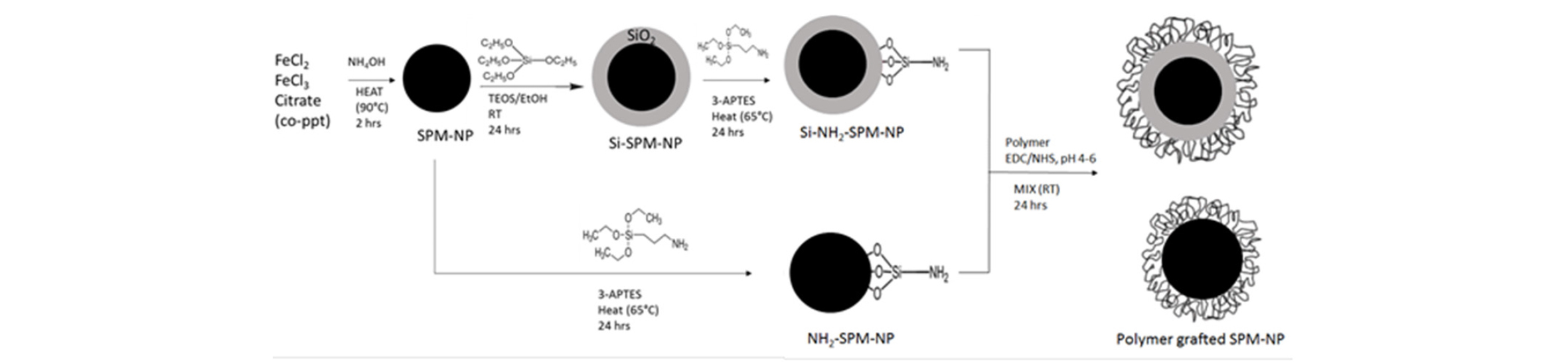
In view of the immense interest on their use, a wide variety of methods to synthesize, to treat their surface, and to characterize the PMNPs have been developed, and extensive literature is available (for review, e.g., Thanh, 2012). The most commonly used PMNPs are of magnetite (Fe3O4), whose surface is coated with a thin layer of polymer or surfactant; or many times, their small aggregate whose average diameter is generally smaller than 100 nm (Fig. 5). It is important that the “primary” particles in the aggregate are separated by the coating so that the magnetite cores are not in direct contact with each other (Yoon et al., 2016). The individual “primary” particles then maintain a magnetic single domain, which is an important requirement for PMNP usage. For many applications, it is not good for the chemical or ion (that is selectively attached to the NP) to be in direct contact with the iron-oxide core. Therefore, a thin shell of silica is inserted between the iron-oxide core and the surface coating (Si-PMNP), as shown in Fig. 5. Because the primary particle size is smaller than 20 nm, both PMNPs and Si-PMNPs show superparamagnetic property (Guimaraes 2009). For more details on the PMNP synthesis methods geared specifically for oilfield use, as carried out recently at University of Texas at Austin, Bagaria et al.(2013a; 2013b), Wang et al.(2014) and Ko et al.(2017) could be consulted.
Magnetic Removal of Microscopic Oil Droplets from Produced Water
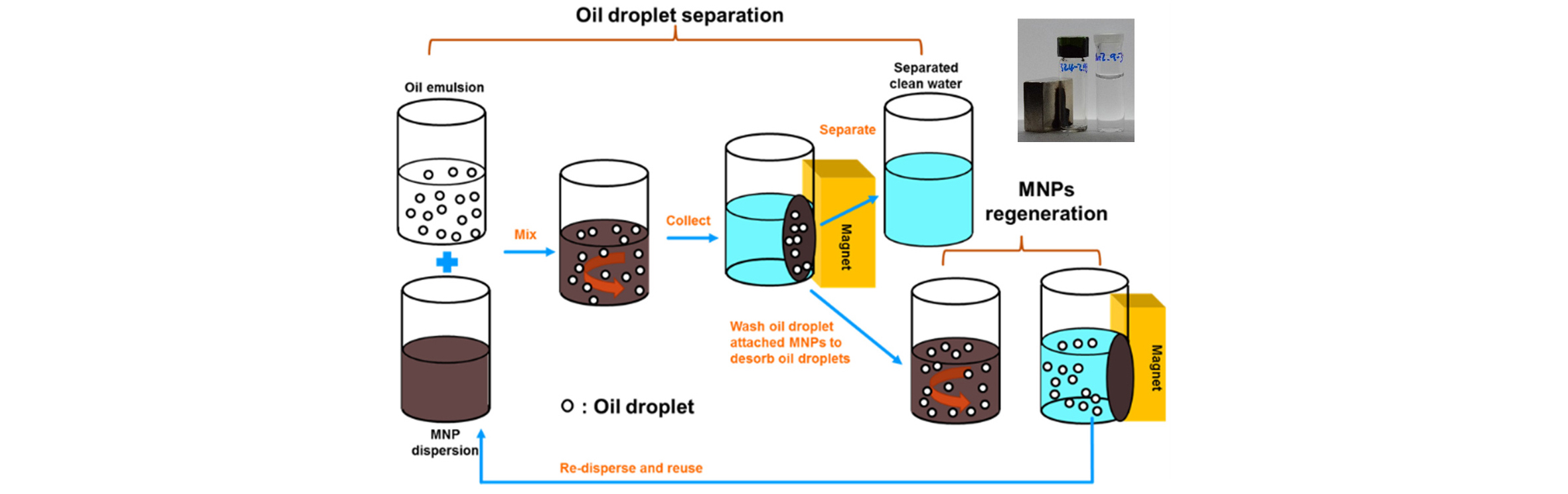
During oil recovery processes, a large volume of water is produced, as much as 20 times of the oil, and the treatment of the produced water for re-use or safe disposal is generally one of the largest oil-field operating expense. One major component of the produced water treatment is the removal of the highly stable dispersed oil. For offshore production, the Convention for the Protection of Marine Environment of the North-East Atlantic (2005) limits the sea discharge for dispersed oil to 40 mg/L while, due to the platform space constraints, compact treatment systems are required. In this context, removal of small oil droplets is especially challenging because long residence times and hence large equipment volumes are typically required. Use of specially surface-coated PMNPs to remove dispersed oil droplets from produced water is a promising way to remedy some of the difficulties that current produced water treatment technologies face. The main attraction for PMNPs is their quick response to move in a desired direction with application of external magnetic field. Magnetic force can be orders of magnitude larger than gravitation, allowing much faster separation of the PMNP-attached, micron-scale droplets from the water. Fig. 6 shows schematically the PMNP-based process to remove the microscopic oil droplets (or the remnant polymer and divalent cations, as described below) from water. The PMNPs are first mixed with the oil droplet-containing water, so that the PMNPs are attached to oil droplets, which are then magnetically separated. After the cleaned water is drained off, the remaining “sludge” of the oil droplet-PMNP combination is treated with an alkali solution to detach the PMNPs from the flocculated oil droplets. The PMNPs can then be regenerated for re-use. Due to its flexibility in surface modification, PMNP can be used for selective removal of a wide variety of target compounds for different water management purpose. Efficient magnetic separation of such PMNPs, employed for “contaminant” removal, can be carried out employing the well-established high-gradient magnetic separation technique which can be designed as a compact system (Gerber et al., 1983).
Modeling the Droplet Removal Dynamics: As the efficiency of the magnetic removal of the microscopic oil droplets will depend on the concentrations and sizes of both PMNP and oil droplets, the external magnetic field strength and other process parameters, modeling of the droplet removal dynamics is an important element of the process development. An initial attempt has been made by Prigiobbe et al.(2015), and a reasonable match with the experimentally measured PMNP settling velocities has been obtained.
Magnetic Removal of Remnant Polymer in Produced Water from Polymer EOR
Partially hydrolyzed polyacrylamide (HPAM) is widely used for polymer flooding, which is a field-proven and one of the most economical EOR processes. As the HPAM usage for EOR increases, the challenge of produced water management is also raised because residual HPAM in produced water could increase total chemical oxygen demand and unwanted viscosity in discharging or re-injecting the water. Use of PMNPs to remove the remnant polymer is a promising way to treat produced water in an environmentally green way with minimal use of chemicals. Ko et al.(2016) successfully employed the PMNPs, in-house synthesized with prescribed surface coating, to develop such a process. The removal efficiency of HPAM from water using the PMNPs depended on the type and concentration of brines, concentration and surface coating of PMNPs, molecular weight of polymer, and how many times the PMNPs are regenerated and re-used. Virtually 100% removal of HPAM from water was feasible, depending on the reaction conditions. The regeneration of spent MNPs, using pH adjustment to recover the reactive sites on the NP surface, maintained above 90% removal efficiency for three-time repeated usages. The electrostatic attraction between negatively charged HPAM polymer and positively charged PMNPs controls the attachment of PMNPs to HPAM molecular chain; and the subsequent aggregation of the now neutralized MNP-attached HPAM plays a critical role for accelerated and efficient magnetic separation.
PMNP-Based Removal of Divalent Cations from Hard Brine
For the polymers (such as the partially hydrolyzed polyacrylamide, in the above section) that are used for chemical EOR processes, their viscosifying ability decreases significantly if the hardness of the brine is high, mainly because of its precipitation which results from the association of the multi-valent cations with anions on polymer chain and the contraction of the chains. It is therefore advantageous to use a polymer solution without any divalent ions. In some reservoir applications, it is difficult to obtain such soft water, especially at the off-shore platforms where the use of seawater is the only cost-effective option. If the hardness of the available, low-NaCl-salinity brine could be eliminated at a low cost, the effectiveness of the polymer flooding would improve significantly. Use of adsorbent NPs for multi-valent ion removal to soften water is highly attractive because of the NP’s large surface area per mass, with a great number of active sites on them. Wang et al.(2014; 2017) investigated Ca2+ removal, using polyacrylic acid (PAA) whose carboxylic group readily attach divalent cations. By grafting PAA to paramagnetic nanoparticles (PAA-PMNPs) and utilizing the high-gradient magnetic separation technique as shown in Fig. 6 above, the Ca2+ adsorption capacity of PAA-PMNPs as high as 57.3 mg/g at pH 7 from the 400 mg/L Ca2+ solution was obtained. The adsorption capacity at high salinity conditions is not as good, because the high salinity screens the negative charges on the surface of PAA-PMNPs, resulting in the formation of NP aggregates. Use of a co-polymer of PAA and poly 2-acrylamido-2-methyl-1-propanesulfonic acid (PAMPS) as the PMNP surface coating is promising, as it brings the synergy between the ability of carboxyl anions along PAA’s flexible C-C chain to selectively capture Ca2+, and the PAMPS ligand’s ability to prevent the chain contraction in high-NaCl environment.
Other Uses of Iron-Oxide Paramagnetic Nanoparticles. Use of Temperature-Responsive Polymer Gel and PMNPBased Heating for Improved Conformance Control
During an EOR process implementation, if a particular reservoir zone can be opened and blocked on command from the surface without an installation of costly hardware in the wellbore, that has a great potential to improve the EOR process performance. In the auto industry, a ferrofluid is employed as an actuator medium whose viscosity would change drastically based upon an externally applied magnetic field. In a similar fashion, the PMNP-crosslinked polymers could potentially be employed as an externally controlled “check valve” fluid, by changing their rheology. Such a technique would allow a precision injection into (or production from) particular zones, by making a localized application of the magnetic field vertically along the wellbore. Thermo-sensitive polymer solution can be transformed to form a gel, by adding PMNPs in the polymer solution and applying external magnetic field oscillation at frequency around 500-1000 MHz. When PMNPs are subjected to such magnetic oscillation, the rapid magnetic pole spinning inside the PMNP generates an intense, localized heat due to the Neel’s relaxation, which is known as “hyperthermia” (Thanh 2012), and is employed in medicine to burn off the cancer cells in cancer patient.
For the envisioned “precision conformance control” technique, a polymer solution with PMNPs added is injected into a certain targeted zone of reservoir and its temperature is changed so that only that zone is blocked with the gelled polymer, as is practiced in medical hyperthermia. Fig. 7 shows schematically the process. Such application then solves the main problem of gel conformance control, i.e., blocking only the high permeability zone while keeping low permeability zones open. Panthi et al.(2015) studied development of such conformance control method using PMNPs to locally heat up thermo-sensitive polymer. They tested four different gel-forming polymers: hydrolyzed polyacrylamide-polyethylenimine (HPAM-PEI), curdlan, methyl cellulose (MC) and hydroxypropyl methylcellulose (HPMC), which are mixed with PMNPs. With the application of magnetic hyperthermia, they showed the gel formation both in bulk state and in porous sandpack.

PMNP-Based Heating for Flow Assurance for Subsea Oil/Gas Pipelines
When oil is produced from a deepsea offshore field, the oil from the usually hot reservoir is subjected to the near-freezing cold temperature near and at the seabed before it reaches the platform. With the sudden temperature drop, often wax or asphaltene particles precipitate out from oil and tend to deposit at the inner surface of the oil transport pipelines, sometimes seriously disrupting the oil production operation. Similarly, the deposition of methane hydrate at the inner surface of natural gas-carrying pipeline is a big problem. To remedy the problem, the electrical resistive heating is applied with a heating jacket wrapping the pipe; or the oil pipe is inserted in another pipe (“pipe-in-pipe”) to create a secure insulation space. As briefly described above, the PMNPs can generate intense localized heat efficiently, when subjected to an external magnetic field oscillation. As the hyperthermia heating can be highly localized with a good energy generation efficiency, Davidson et al.(2012) and Mehta et al.(2014) investigated the feasibility of imbedding PMNPs in the paint which coats the inner surface of the subsea oil pipeline. By applying magnetic field oscillation to the “nano-paint”, a thin, heated layer of wax (or asphaltene, hydrate) can be generated at its boundary with the pipe’s inner surface, which will make the deposit to detach from the pipe wall and be carried downstream by the flowing oil. Mehta et al.(2014) proposed to use a small, free-floating, battery-operated magnetic oscillation emitter (“intelligent pig”) which flows with the oil, thereby not interrupting the normal oil transport operation. In addition to the investigation on the heat generation capacity of different PMNPs in different dispersing medium, their preliminary feasibility simulations suggest that such use of an intelligent pig is quite achievable.
Use of PMNPs as “Contrast Agents” for Enhanced Reservoir Imaging
Active research efforts are currently on-going on the use of PMNPs to obtain more accurate information on the reservoir rock and fluids’ in-situ properties and on the dynamics of the resident and injected fluids. Broadly, two different approaches were taken: (1) Addition of a NP dispersion in a portion of the injection fluid bank, for waterflooding or EOR, and the detection of their location and movement remotely; and (2) addition of a NP dispersion in the injected fluid which then detects certain properties of the reservoir rock and/or fluids, and carries the information with the nanoparticles. When the particles are produced, they can be “interrogated” to retrieve the data, which is known as either “intelligent tracer” or “nano-reporter”. Below, the first approach of the remote reservoir imaging will be briefly described.
When the PMNPs are subjected to the external magnetic field, they magnetize and generate tiny induced magnetic field around them. Therefore, when a bank of a PMNP dispersion is injected into a reservoir or a fracture and is then subjected to an external magnetic field oscillation, the NP ensemble generates a “halo” of induced field which can be remotely detected at an observation well, as schematically shown in Fig. 8. For the oscillatory magnetic field generation and the measurements of the induced field response, the existing technology of the crosswell electromagnetic (EM) tomography can be utilized (Rahmani et al., 2014). While the EM tomography is currently employed to identify a reservoir zone or a fracture which has an electrical conductivity contrast, the aim of the proposed use of PMNP is to create a zone of magnetic susceptibility contrast and delineate its location and movement. Once the induction responses are measured at the observation well, a set of Maxwell equation solutions will be obtained with the assumed locations/configurations of the NP dispersion zone; and an inversion algorithm is employed to identify the exact location/configuration (Rahmani et al., 2014). The feasibility simulation study of Rahmani et al.(2015) shows that, with use of low-frequency magnetic oscillation (< 100 Hz), if the magnetic susceptibility contrast is of the order of ~ 0.1, meaningful measurements of induction responses are possible.

Another potential application of PMNP for remote detection of the presence of oil in subsurface formations has been explored (Prodanovic et al., 2010), which relies on the targeted delivery of PMNPs to the oil/water interfaces of oil ganglia in the reservoir. In the proposed method, once the PMNPs are successfully delivered and attached to the interface of oil meniscus in the rock pore, the external magnetic field oscillation is applied. As described earlier, the external field gradient will make the PMNPs to oscillate, causing the oil/water interface fluctuates and generates a tiny density wave. Such interfacial fluctuation and the resulting acoustic wave could be detected and analyzed.
Conclusions
Nanotechnology is a truly huge area with publication of thousands of papers and patents, every year. In addition to the above examples of application development carried out at University of Texas at Austin, there are other nanotechnology areas that can be gainfully employed for upstream oil applications. In developing all these exciting applications, two hurdles need to be overcome. First, the nano materials are still relatively expensive for certain applications such as EOR. On the other hand, those reservoir applications require a large volume of material, which potentially could lower the manufacturing cost. Another hurdle is the environmental concern when we consider injecting nanoparticles into the reservoirs. Careful life-cycle considerations should be made in developing those injectants which should be environmentally benign, such as silica and iron-oxide nanoparticles. Learnings from other industries, which carried out extensive studies in this regard, should again be carefully studied and utilized. With careful adaptation of the huge advances made by other industries, the future of nanotechnology use for the upstream oil industry is judged to be bright.
